
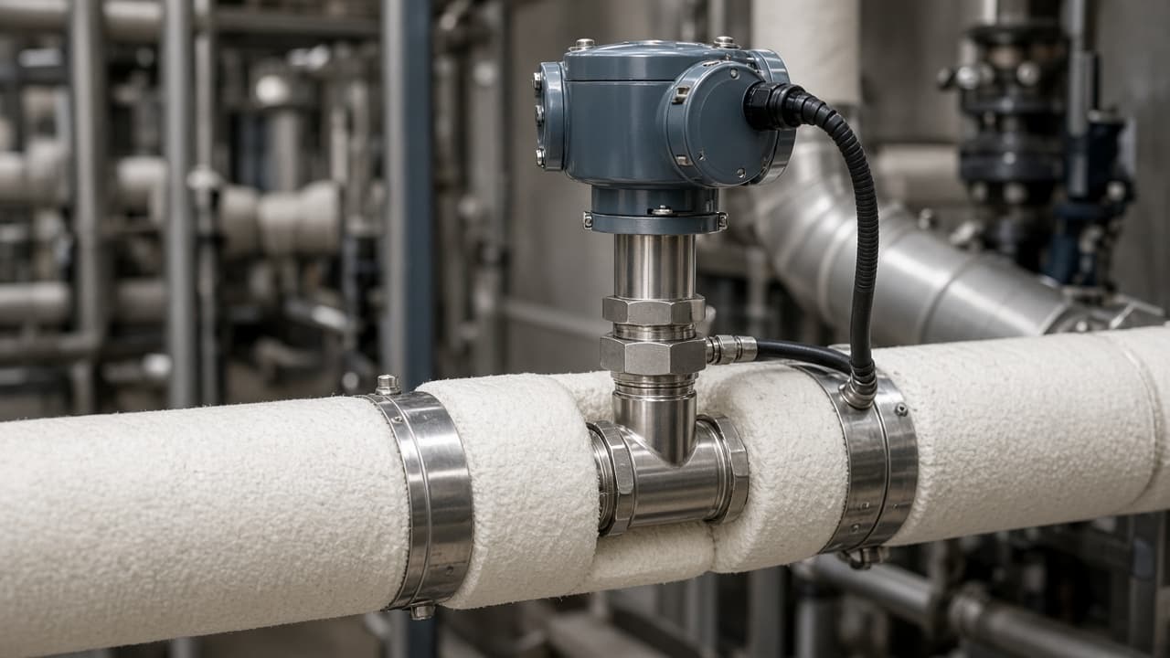
Temperature loops fail in two quiet ways. The sensor may be accurate in a bath and still miss the fluid temperature in the line because the thermowell is too short, sits in a dead zone, or conducts heat into the wall. Separately, a well that is long enough for immersion can still be a vibration risk when flow excites the stem near its natural frequency.
This article covers thermowells on process piping and vessels—not pyrometry on furnaces, and not the spray-mixing problems of desuperheaters, though both also care about where the sensing element sits.
Immersion before electronics
The sensing element needs enough of the well immersed in the flowing fluid for conduction through the tip to dominate conduction into the nozzle and pipe wall. Industry practice and many OEM installation notes emphasize adequate immersion and avoiding wells that barely clear the inner wall. A short well often produces a reading that lags and sits between fluid and metal temperature. Operators then widen controller deadbands or blame the PID tune for a sensor geometry problem.
Placement also matters. Wells in stratified headers, near partially open valves, or in the lee of fittings sample a local stream, not the bulk. Moving the well a few diameters can change the control story more than swapping the transmitter.
Wake frequency and mechanical integrity
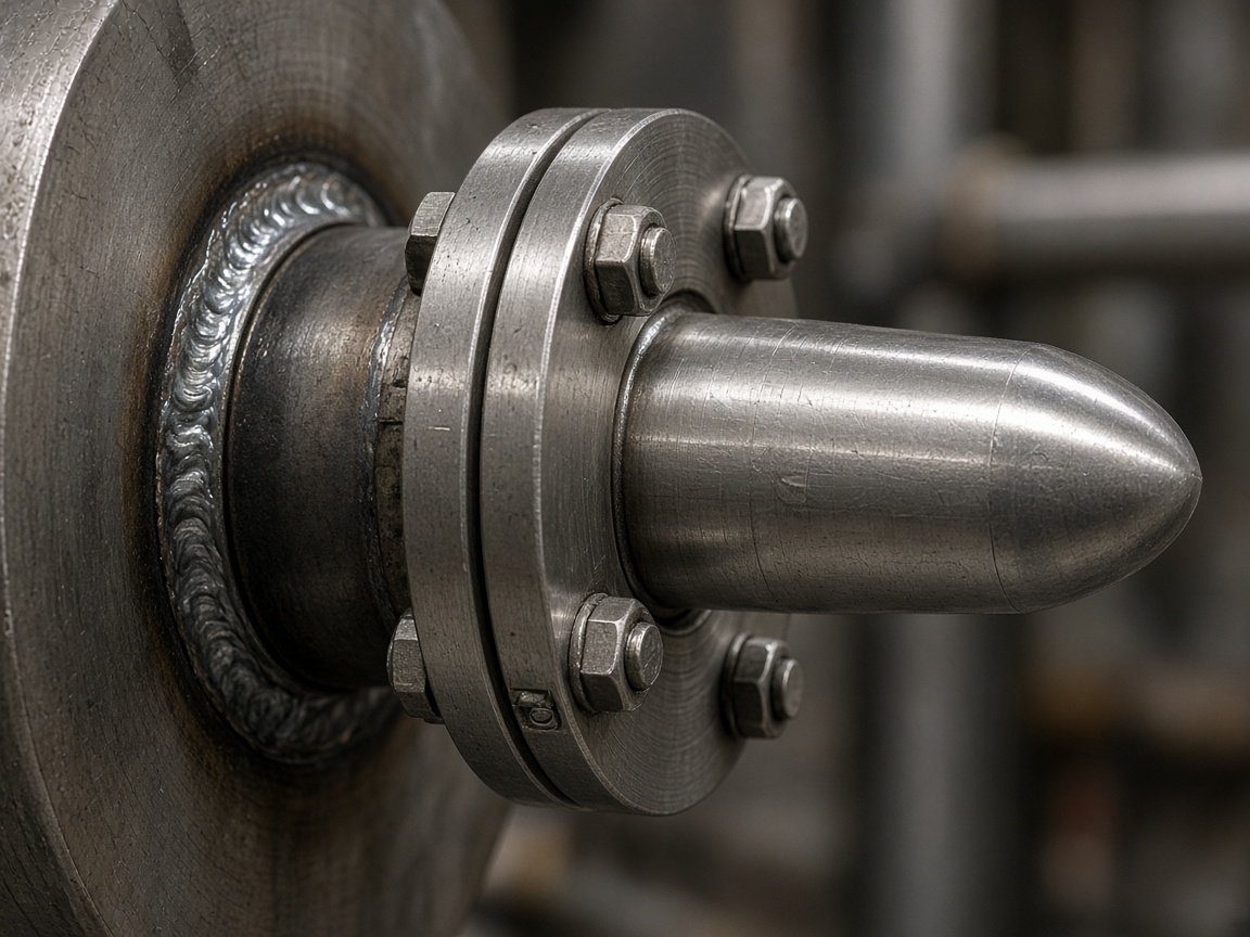
Flow past a thermowell sheds vortices. When the shedding frequency approaches the well’s natural frequency, vibration amplitude can rise enough to crack the stem or fatigue the connection. Design standards for thermowells (commonly discussed in the ASME PTC 19.3 TW family of guidance) treat wake frequency, strength, and frequency ratio as design checks—not as optional paperwork after a well has already failed in service.
Practical implications for plants:
- Do not lengthen a well for “better immersion” without revisiting the vibration calculation for the new geometry and the actual velocity range.
- Do not raise flow rates after a process change and assume the old well still sits in a safe frequency band.
- After a broken well, inspect for root cause (vibration, corrosion, installation) before installing an identical spare.
What to put on the data sheet
Tag number, well material, insertion length, process connection, design velocity and fluid, and the date of the last wake-frequency review belong with the instrument record. A calibrated RTD behind an undocumented well is only half of a measurement system.
When a loop hunts or never quite matches a nearby reference probe, check immersion and location before rewriting the control narrative. The fluid is where the energy is. The well is how much of that energy the sensor is allowed to see.