
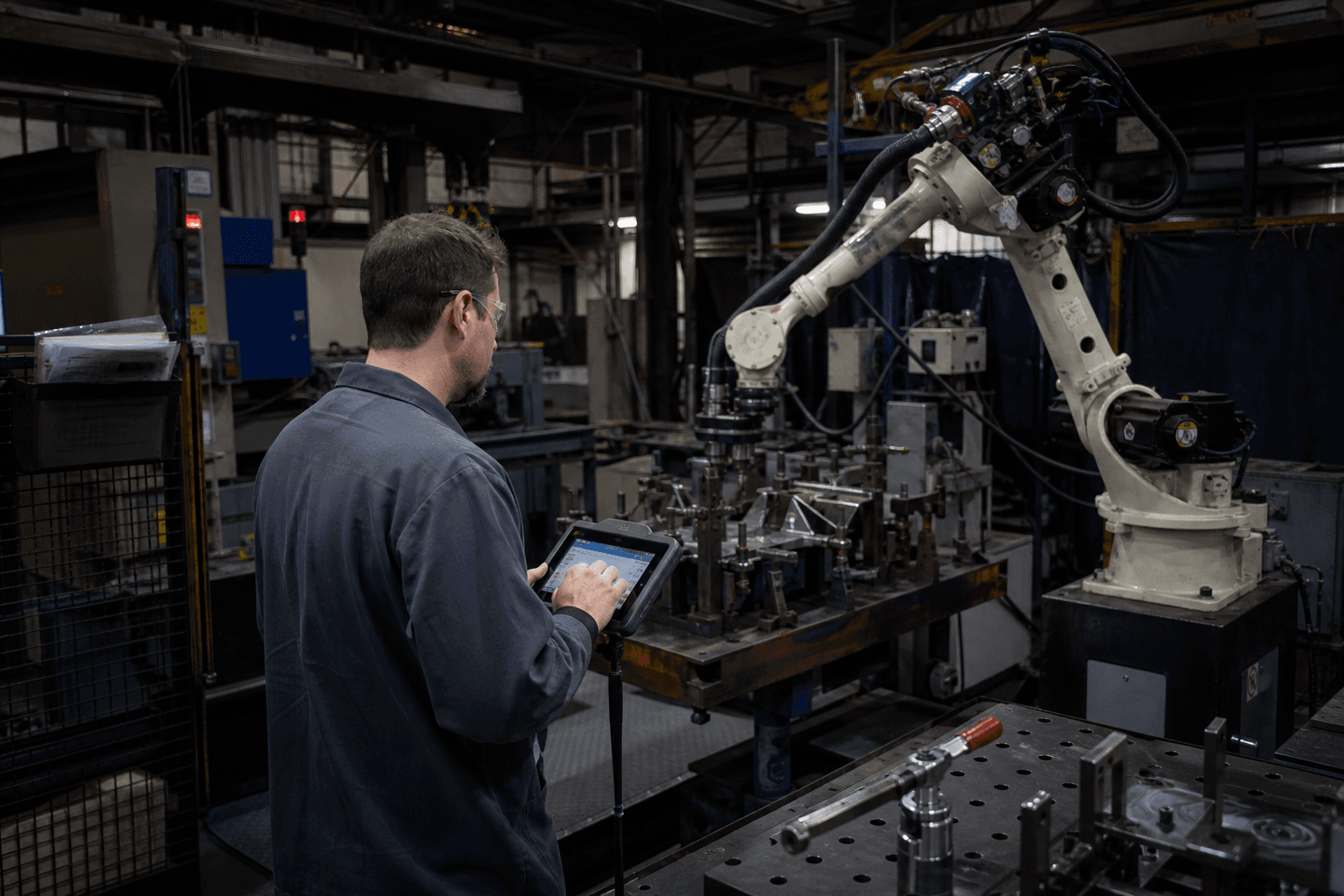
A robot that has been repaired and returned to service is not the same robot that was last verified. This is obvious when stated directly, and consistently overlooked in the daily pressure of getting production back online. The original factory acceptance test covered the robot in an as-new state with calibrated tooling, a verified program, and a safety function test that signed off before the cell ever shipped. A repair that touches a servo motor, a joint gearbox, a force-torque sensor, or a complete arm replacement changes the mechanical and electrical state of the system in ways that the original FAT cannot cover because it predates the failure.
The gap between repair completion and verified-safe production readiness is the subject of this piece. It is not about the FAT methodology itself or about commissioning new cells from scratch. It is about the specific, frequently skipped verification steps that apply when a robot returns to service after a repair event—and the production and safety consequences that accumulate when those steps are abbreviated.
What a repair actually changes
To understand the verification requirements, it is necessary to be specific about what a repair changes. Different repair types create different verification obligations.
A servo drive replacement—the most frequent non-consumable repair on an industrial robot—changes the electrical drive characteristics delivered to the motor. A new drive of the same model and firmware version should produce nominally identical torque-speed curves to the replaced unit. But firmware version parity is not always verified during emergency repair procurement, and even within the same firmware, drive-to-drive variation exists. The immediate consequence is a potential change in the torque ripple and dynamic response at that axis, which may or may not manifest as observable path deviation at production speed.
A joint gearbox replacement changes the mechanical compliance and backlash at that axis. Gearbox-to-gearbox variation within the OEM's specification range is real. A new gearbox with backlash at the high end of the allowed specification will produce small but measurable path deviations compared to the worn gearbox it replaced—which had different backlash characteristics because of wear, not because of manufacturing variation. Neither the worn gearbox nor the new one may be outside specification, but the robot's calibrated model was built against the previous gearbox, not the new one.
A complete arm assembly replacement—J1 base, J2 lower arm, or J3 upper arm—is a more significant event. The arm contains the mechanical structure whose stiffness, weight, and centre-of-gravity position were characterised during the original calibration. A replacement arm from the same OEM and model series should be within specification, but physical replacement requires re-mastering: verifying that the joint zero position references are correctly established for the new mechanical assembly. An arm that is installed and re-mastered incorrectly produces path errors that grow with reach distance from the tool centre point.
A force-torque sensor replacement changes the calibration of the force sensing function. This matters most in applications where the robot uses force feedback—assembly, grinding, polishing, precision insertion—because the sensor calibration coefficients that map raw transducer output to calibrated force and torque values are specific to the individual sensor, not to the sensor model.
The mastering verification: what it is and why it is skipped
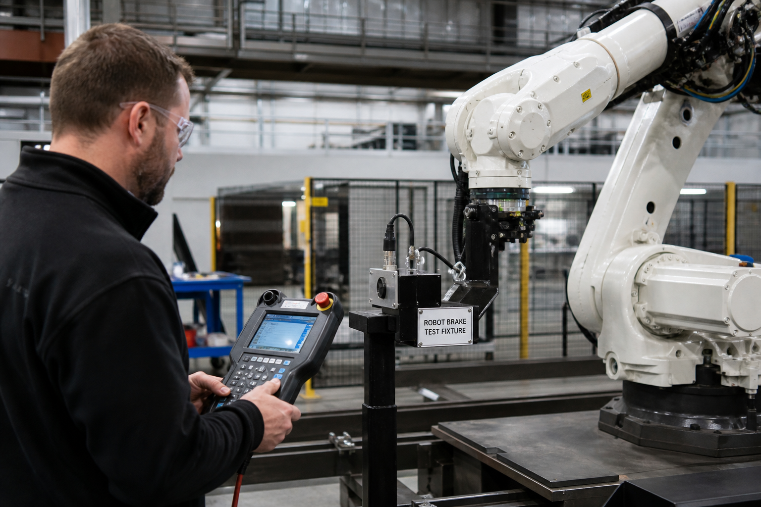
Robot mastering is the process of establishing the correspondence between the joint position encoder reading and the physical mechanical position of each joint. On most modern industrial robots, mastering is performed using a mastering fixture—a precision reference that positions the joint at a known angle—and a software procedure that stores the encoder value at that position as the reference zero for each axis.
The mastering procedure is called for whenever a component that could affect the encoder-to-joint correspondence is replaced: typically a motor, motor brake, motor encoder, gearbox, or arm link. The OEM service documentation is explicit on this point. Yet mastering is the step most frequently abbreviated in repair events, for two reasons.
The first is time. Mastering on a six-axis robot using a traditional mastering fixture and the controller's built-in procedure takes thirty to ninety minutes, depending on robot configuration and access. Under production pressure, that time is perceived as a delay rather than a safety prerequisite. The technician who was trained to say "mastering is done" after pressing a few pendant buttons without installing the fixture is confirming a mastering state that may not reflect the physical reality of the repaired robot.
The second is the assumption that the encoder value was not disturbed. For a servo drive replacement, this assumption is sometimes correct—if the motor was not removed and the motor brake held position throughout the drive replacement, the encoder value at the controller may still reflect the physical joint position. But "sometimes correct" is not a verification. The only way to know whether the encoder-position correspondence is intact is to verify it against the mastering fixture, not to assume it.
A robot running in production with an unverified mastering state is a robot whose TCP position relative to the workframe is unknown to within the magnitude of the mastering error. For a welding robot with a 10 mm mastering error at J1 at a reach of 1.5 metres, that is a weld start position error of 26 mm—large enough to miss the joint entirely or to produce a heat-affected zone in the wrong location. For an assembly robot handling tight-tolerance insertions, it is a crash.
Brake testing: the check that ISO 10218 requires but plants skip
Every joint of an industrial robot contains a motor brake. The brake is normally held off by electrical supply—it is a fail-safe device that engages when power is removed or when the safety function calls for it. The brake holds the joint stationary when the servo drive is de-energised, both during intended stops and during E-stops.
ISO 10218-1 requires that brake performance be verified as part of the robot acceptance into service. The intent is that brake holding torque is adequate to prevent joint drift when the robot is stopped in the worst-case payload and arm position. In practice, this test is performed once at original commissioning and then not repeated unless the brake or motor is replaced.
After a motor replacement, the brake is an integral part of the replaced assembly and its holding torque is unknown. After a motor brake replacement alone—when the brake housing, brake disc, or electromagnet is replaced as a separate service—the holding torque may be affected by the seating state of the new brake components, which improves over the first hundred operating cycles as surfaces bed in.
A brake hold test verifies that the joint does not drift when the servo is de-energised and the robot is positioned at the worst-case gravity loading position for that axis. For a vertical-reach robot with a 10 kg payload, the worst-case position for J2 is typically at 90 degrees of shoulder joint angle with the arm fully extended horizontally. With the drive de-energised and only the brake holding, the joint should not move. If it does, the brake is not adequate for the specified payload, and the repair is not complete.
This test takes approximately five minutes per joint. For a six-joint robot, thirty minutes. It is not in the OEM repair procedure card. It should be in the plant's repair verification standard.
Path verification: how much deviation is acceptable
After mastering and brake verification, the path verification step confirms that the robot's TCP motion matches the programmed path within the tolerance required for the application. Path verification is not a production trial run. It is a controlled measurement using a reference program and a measurement reference—typically a precision gauge pin in the tool mount or a measurement fixture that the cell was originally commissioned with.
The reference program moves the robot through a sequence of positions that exercises the full workspace envelope used in production—near reaches, far reaches, overhead reaches—and compares the actual TCP position at each taught point to the expected value. The acceptable deviation is application-specific: a welding application may tolerate ±1.5 mm; a laser-cutting application may require ±0.3 mm; an assembly application with precision pin insertion may require ±0.15 mm.
If path verification shows deviations outside the application tolerance, the response before production restart depends on the source. Mastering error—consistent offset at all positions—indicates a mastering correction is needed. Scaling error—deviation that grows with reach distance—indicates a kinematic model mismatch that may require OEM recalibration. Axis-specific deviation—concentrated at the replaced joint—indicates that the replaced component may be outside specification and requires discussion with the OEM.
In each case, the path deviation is a measured number, not an opinion. A plant that skips path verification and discovers path deviation through production scrap is measuring the same thing, at higher cost, in the wrong place.
Safety function verification: what changes after a repair
Collaborative robot and safety-rated function verification is the area where repair events create the highest potential for undetected regression. Safety-rated functions—speed monitoring, joint position limiting, tool zone monitoring, force limiting—are implemented in safety controllers and safety-rated drives that have specific hardware requirements. When a safety-rated component is replaced, the safety function implemented in that component must be verified to perform as specified.
For a standard industrial robot in a guarded cell, the relevant safety functions after a motor or drive replacement typically include: E-stop category response time, safety-rated soft-axis limiting, and motor brake function (which was covered above). These are verifiable with the standard acceptance test procedures.
For a collaborative robot or a robot with integrated safety-rated functions, the scope expands. A force-limiting cobot that has had its motor or force sensor replaced needs its force-limiting threshold verified under the specific conditions for which it was risk-assessed: approach speed, payload weight, contact geometry. Verification is not "run the cobot at slow speed and see if it stops when I push it"—it is a measurement against the specified threshold with a calibrated force measurement device.
Many plants do not have the tooling to perform this verification in-house and rely on the OEM or system integrator to return for post-repair safety verification. The gap between repair completion and the OEM visit is a period during which the robot either sits idle—impacting production—or runs without completed safety verification—creating safety risk. Managing this gap requires either having in-house verification capability or having the OEM safety verification visit scheduled before the repair is complete, not after.
The re-commissioning record: what to document and why
Every robot repair event that triggers re-commissioning verification should produce a signed, dated record with the following minimum content: the repair that was performed and the replaced components, the mastering procedure performed and by whom, the brake test result for any affected joints, the path verification measurement data against the application tolerance, and the safety function test results with comparison to the original acceptance values.
This record is not an administrative burden. It is the evidence base for three things. First, it demonstrates due diligence in the event of a cell incident post-repair. A plant that can show a complete verification record for the last repair event is in a very different regulatory and legal position than a plant that cannot. Second, it provides a trend dataset. If path verification consistently shows the same axis drifting toward the tolerance limit after repairs, that pattern indicates a systematic issue—calibration model mismatch, component variation, tool mounting instability—that can be addressed before it produces scrap or a safety event. Third, it supports the conversation with the OEM during warranty or service contract discussions about what was and was not covered by the repair.
The robot that is repaired, re-mastered, brake-tested, path-verified, and safety-function-verified with a completed record is a robot that is known to be in the same verified state as it was before the failure. That is the only condition under which the repair is finished.