
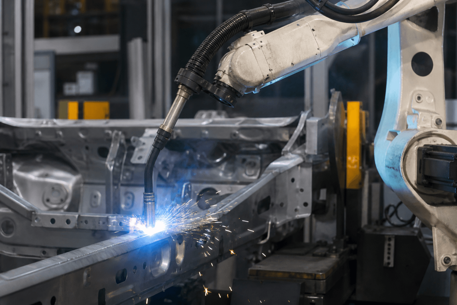
A MIG/MAG robot cell is sold as a path and a power source. The arc exists at a copper tip, a stick-out length, and a liner that has been filling with drawing soap and helix for a month. When the weld goes porous or the robot "hunts" along the joint, the first suspects are TCP and seam tracking. Those matter. They are not the first consumable to measure.
This is not adaptive welding theory, not laser keyhole monitoring, and not a dress-pack cable story. It is the last half-metre of the wire path.
Stick-out is a process parameter
Electrical stick-out (contact tip to work) sets resistive preheat in the wire and the current density at a given WFS. Robots hold stick-out only if the torch angle, TCP, and worn tip length stay where they were taught. A tip that has receded from spatter and dressing, or a nozzle full of slag, changes stick-out without a program change. The synergic curve is then running a different weld than the one that passed PPAP.
Measure stick-out on a coupon at production posture, not with the arm at home. A torch that clears the fixture at home can be stubbing or stretching at the far tack.
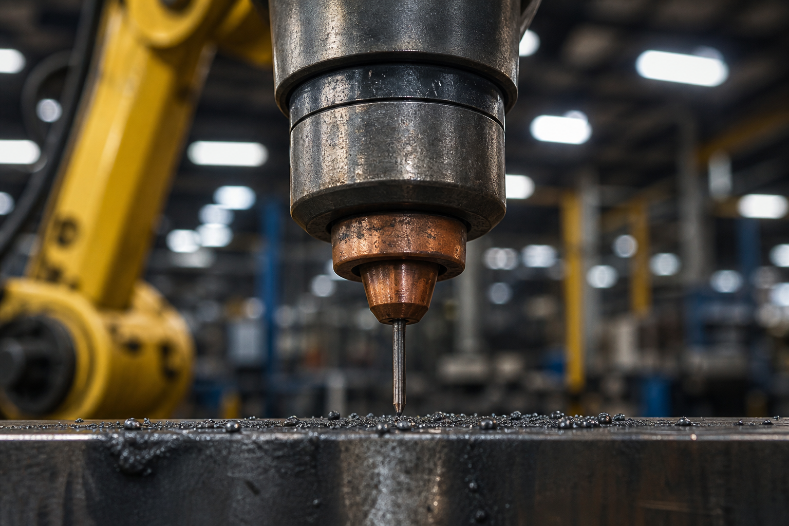
Liners and tips are geometry
A liner with bird-nesting, kinks at the robot wrist, or the wrong ID for the wire diameter adds feed resistance. The feeder current rises; the operator turns up drive roll pressure; the wire now has a cast that the tip cannot straighten. Arc start failures and wandering beads follow. Replacing the tip without replacing the liner is how the same fault returns in two days.
Contact-tip bore wear is an oval that lets the wire wander inside the tip. Current pickup becomes intermittent. Spatter increases. Change tips on a weld count or on a resistance/feed-force trend, not when someone notices the bead.
Gas flow at the nozzle is the third geometry. A spatter-clogged diffuser that still shows 15 L/min on a gauge at the regulator is not 15 L/min at the puddle. Check at the nozzle with the robot in the weld pose.
After a liner change
Re-teach is rarely required. Verification is: feed force or motor current on a known WFS, a start/stop coupon, and stick-out against the WPS. Skipping the coupon because "it is only a liner" is how a reversed liner direction becomes a shift of burn-through.
The robot repeats the path. The weld repeats only if the wire, the tip, and the stick-out repeat. Service those three as process, not as housekeeping.