
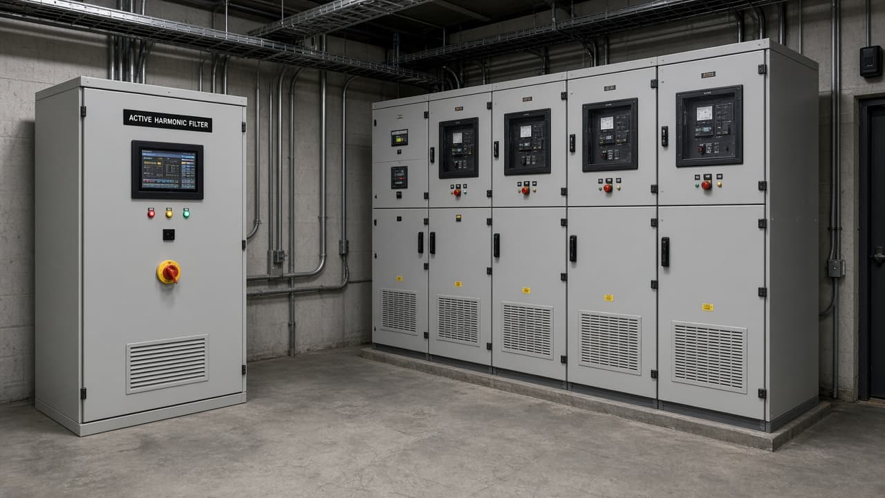
Variable-frequency drives, rectifiers, and other non-linear loads inject harmonic currents into plant distribution. Active harmonic filters (AHF) measure those currents and inject opposing current so the feeder side looks cleaner. They are not the same product as detuned passive capacitor banks used for power-factor correction, though both may appear in the same electrical room.
PFC capacitor bank detuning and regenerative VFD DC-bus topics cover related power-quality surfaces. This piece is about AHF application basics: sensing, sizing, and coordination.
Sensing comes before software
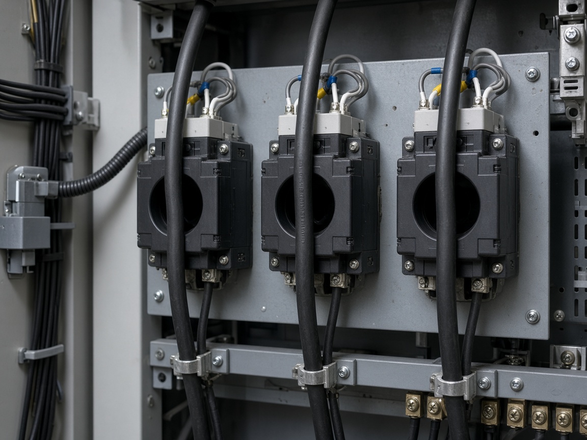
Most AHF designs depend on current transformers that sample the load (or the line, depending on topology and vendor instructions). If CTs are on the wrong side of the filter connection, undersized, saturated, or wired with incorrect polarity, the controller optimizes against a fiction. Installation manuals emphasize CT ratio selection, phase orientation, and clearances for a reason: the filter cannot cancel what it cannot measure.
Spectrum and rating
AHF continuous current rating must cover the harmonic ampere demand—not only the fundamental load current someone remembered from a nameplate. A site survey with a power-quality analyzer (or equivalent) that captures typical and peak operating modes is the usual basis for selection. Background distortion from the utility or neighboring feeders also matters; a filter sized only for one VFD lineup can still leave voltage THD high if the bus is already dirty.
Multiple filters, passive banks, and generator sets on the same bus need coordination so control loops and resonances do not fight. Vendor application notes and the plant single-line diagram belong in the same MoC package when the filter is added or relocated.
Commissioning that proves the buy
As-found and as-left harmonic spectra at agreed metering points, verification of CT wiring, and thermal checks under representative load are the minimum evidence that the cabinet is doing electrical work—not only showing a green HMI. If THD targets are contractual, write the metering location into the acceptance test. Measuring at a convenient panel that is not the point of common coupling (or the agreed bus) creates arguments later.
An active filter is a controlled current source with a sensing problem attached. Solve sensing and sizing first; the algorithm only amplifies whatever truth—or error—the CTs provide.