
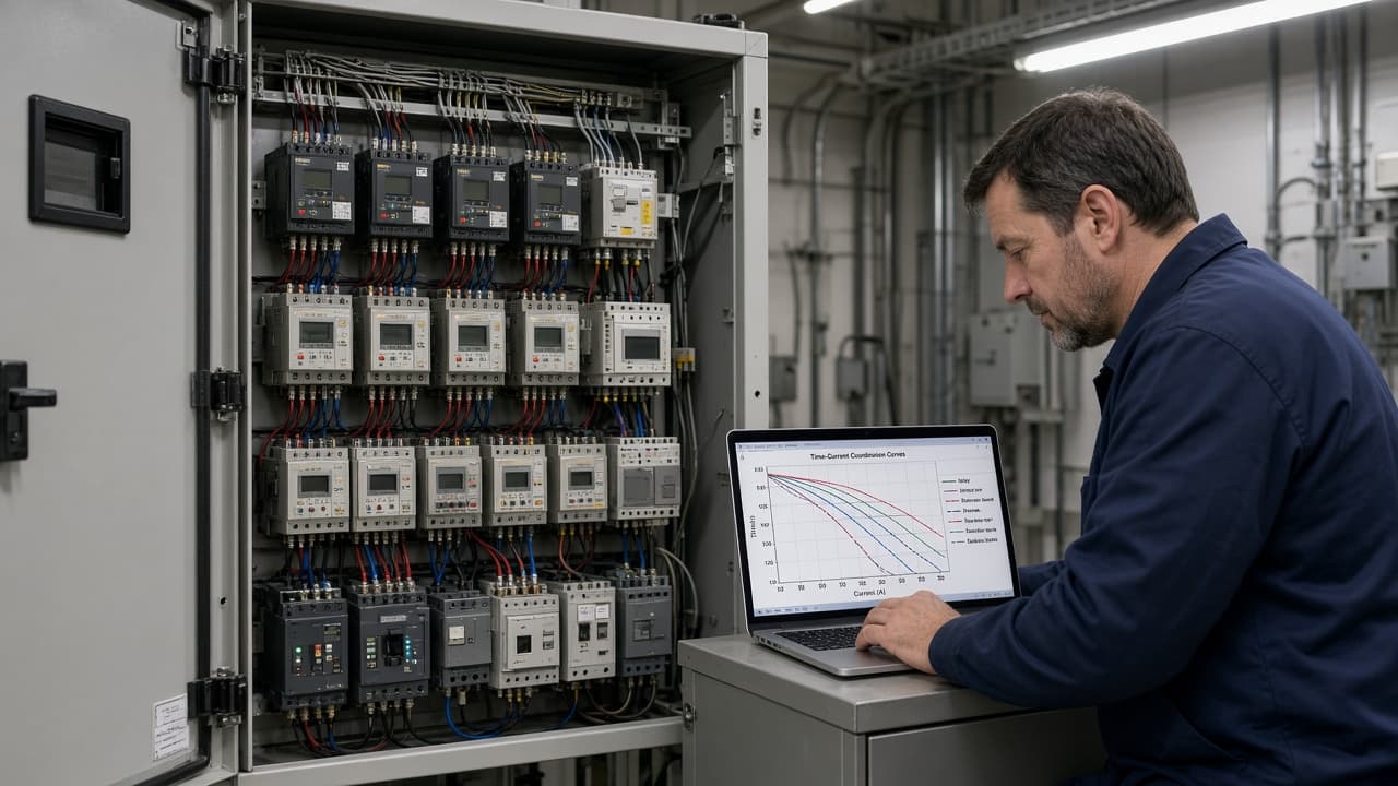
CT saturation essays own secondary honesty. Trip-report decode owns what the relay said after the fact. This page is the study that should have been current beforehand: time-current grading of phase and earth-fault overcurrent devices from load out to the source.
Selective coordination means the nearest device operates first; upstream devices wait with intentional margin and provide backup if the primary fails. Protection engineers plot relay and fuse curves on a common current base, set the farthest device for the shortest practical time at maximum fault level, then verify behavior at minimum expected fault current. Pickup must respect load, motor starting, and transformer inrush so the curve protects without nuisance trips. Grading margins between series devices are not optional decoration—recommended practice leaves explicit time separation so manufacturing tolerance and CT error do not erase selectivity.
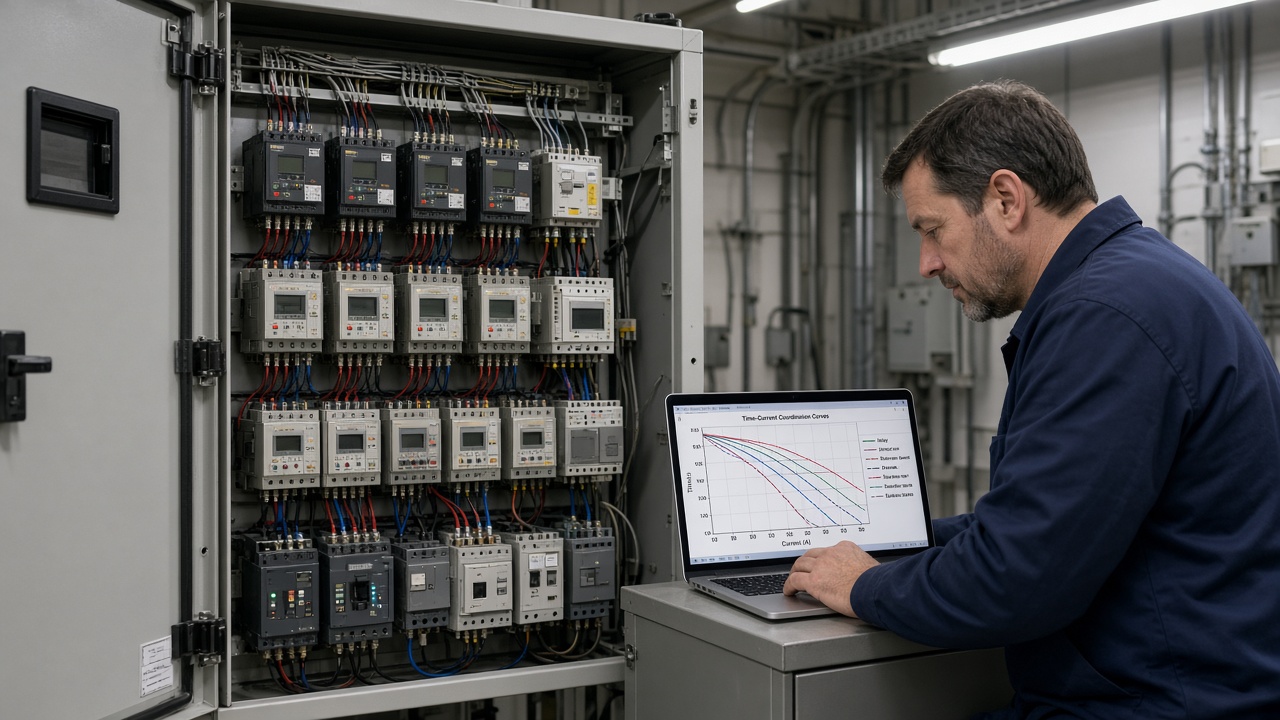
Re-open the study when the system changes:
- New or resized transformer, feeder, or large motor
- CT ratio or relay firmware/model swap
- Fuse type change or breaker trip-unit replacement
- Added generation or significant fault-level shift
Plot primary amperes consistently. Check that downstream pickups are not higher than upstream on a primary basis. Document settings, curve family (standard inverse, very inverse, definite time, and so on), and the accepted grading margin in the protection file the next outage crew will trust.
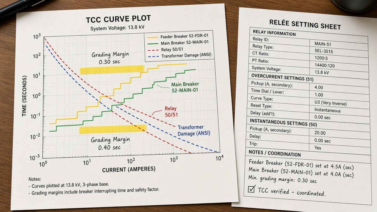
A green “relay tested” sticker is not a coordination study. If the main clears every feeder fault, the settings won the race they were never supposed to enter.