
A pipeline that has never been pigged is a pipeline whose internal condition is unknown. External inspection methods—above-ground cathodic protection surveys, close-interval potential measurements, direct examination excavations—characterise the corrosion threat from outside and in isolated locations. They cannot see internal corrosion that develops on the bottom of a wet-gas line, pitting that concentrates at a weld heat-affected zone, or mechanical damage from a previous construction crew that was never reported. The only inspection method that travels the full bore length and reports what it encounters at centimetre resolution is the instrumented inline inspection tool, commonly called the intelligent pig.
The decision to pig a pipeline is an integrity management decision, not a maintenance scheduling one. Under risk-based pipeline integrity frameworks—API 570, API 1160, or the European EN 16348 equivalent—the inspection interval and the tool selection are driven by a threat assessment: what damage mechanisms are active, at what rate, and what is the consequence of undetected growth between inspection cycles. A pigging program built on those foundations is a defensible integrity argument. A pigging program scheduled at fixed calendar intervals because "we always pig every five years" is a compliance gesture.
The three major pig classes and what they find
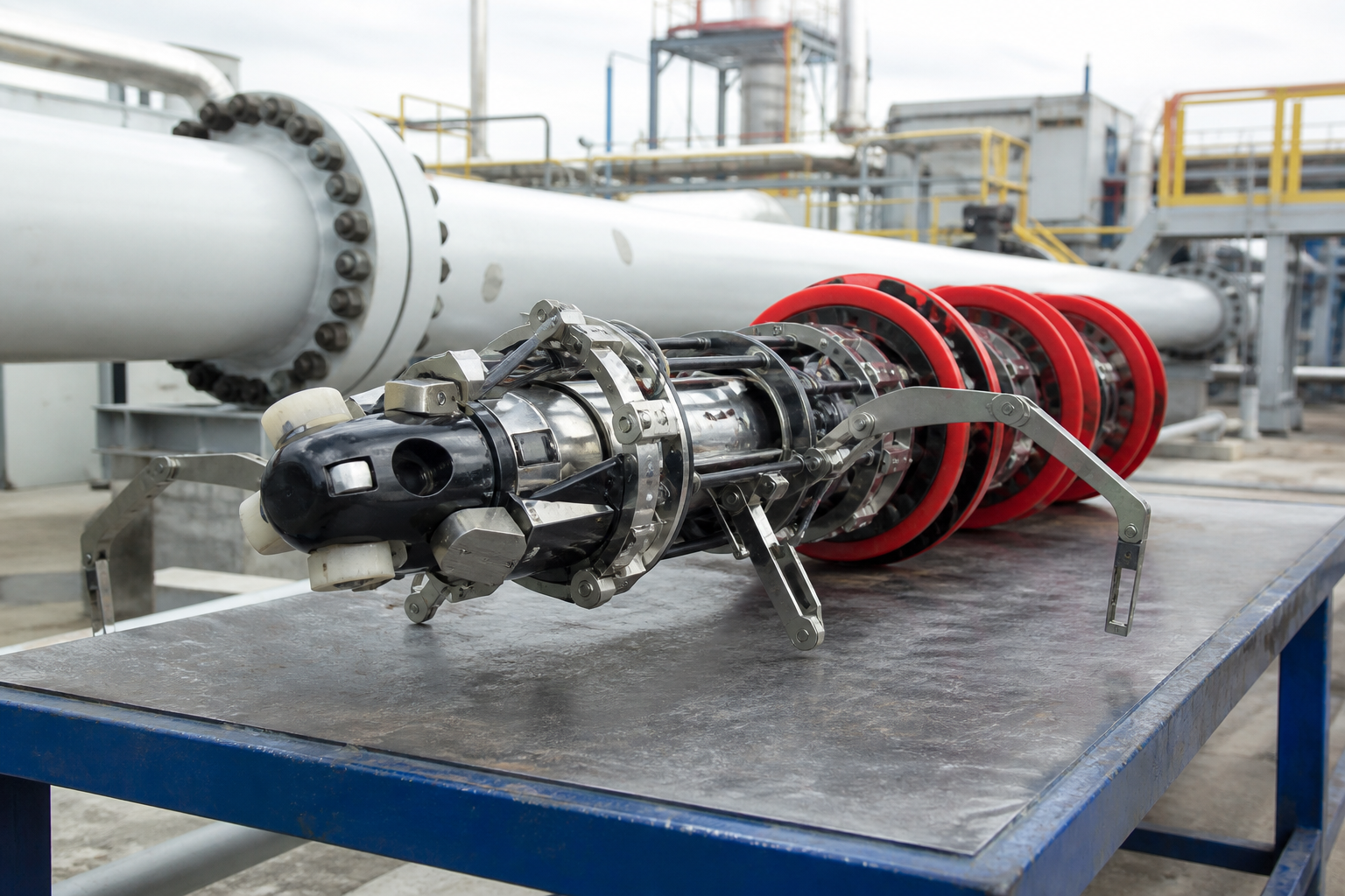
Magnetic flux leakage is the most widely deployed inline inspection technology. The tool magnetises the pipe wall to near-saturation using permanent magnets or electromagnets, and sensors in the tool detect the flux leakage that results where the wall is thinner due to corrosion, erosion, or mechanical damage. MFL provides high-speed coverage—tools can run at pipeline velocities—and generates a continuous axial and circumferential flux signal that, after analysis, produces a feature list with position, estimated length, width, and depth for each anomaly.
The limitation of MFL is that signal amplitude is proportional to metal loss volume, not to remaining wall thickness directly. A wide shallow pit and a narrow deep pit with the same metal loss volume produce similar MFL signals. Distinguishing them requires either high-resolution MFL with circumferential sensors—Hi-Res MFL—or a second tool run with a technology that measures geometry rather than flux.
Ultrasonic testing inline inspection overcomes the volumetric limitation by directly measuring remaining wall thickness at each sensor position. Dry contact UT tools use focused transducers pressed against the pipe wall; liquid-coupled UT tools operate in liquid-filled pipe and transmit ultrasound through the product. UT data is geometrically more interpretable than MFL data, but UT tools have operating constraints that MFL tools do not: they require liquid coupling or dry contact with sufficient spring force, they are sensitive to gas pockets and wax buildup, and they have a minimum run speed below which data quality degrades.
Geometry tools—caliper pigs and deformation tools—measure bore geometry rather than wall condition. They detect dents, ovality, buckles, bore restrictions, and valve partial-closures. A geometry run is often specified before an MFL or UT run to confirm that the bore is clear of obstructions that would prevent the instrumented tool from passing safely. It also finds mechanical damage that MFL detects as deformation anomalies and UT may miss entirely if the deformation does not produce wall thinning.
Launcher and receiver condition: the underrated prerequisite
An intelligent pig that fails to complete its run, arrives damaged at the receiver, or arrives with partial data is worse than no pig run, because it may be interpreted as a pass when it is not. Launcher and receiver condition is the first thing an experienced pigging engineer checks before accepting a run scope.
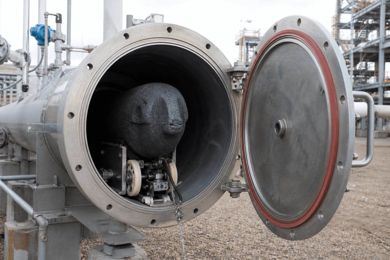
The launcher is the pressure vessel from which the pig is inserted into the pipeline under operating pressure. A launcher with a bore restriction—a weld bead, a worn pig stop, a gasket that protrudes into the bore—can damage the pig at insertion. A launcher with internal corrosion that contaminates the product stream can foul the pig sensors before the tool has travelled its first kilometre. A launcher with an inadequate isolation valve that allows bypass flow around the pig during launch results in a pig that starts the run at a lower speed than planned and may stall in the first section.
The receiver is where the pig is decelerated, isolated, and removed. A receiver that does not provide sufficient pig deceleration length results in high-impact pig arrivals that damage sensor arrays or—on a worst-case run with product-propelled pigs—create a projectile hazard during opening. Receiver internal corrosion that was never addressed because "pigs only exit here, they don't run in here" has contaminated inspection tool electronics on arrival and invalidated the run data.
A launcher and receiver inspection prior to a scheduled pig run should include: bore measurement, internal visual inspection, valve functional test, pig stop condition, vent and drain valve operability, and kicker connection integrity. This inspection is not typically in the pig service contractor's scope unless it is explicitly specified. The plant team that assumes the contractor covers launcher/receiver prep is the team that gets the call on pig arrival day explaining why the run needs to be repeated.
Run planning: speed, product conditions, and bypassing
MFL and UT inline inspection tools have velocity operating windows. Outside those windows—too slow or too fast—data quality degrades. The pig speed depends on the product flow rate and the tool bypass configuration. Most instrumented pigs use a bypass disc or sealing cups that create a differential pressure across the pig, which both propels it and sets its speed. Increasing bypass area reduces pig speed; decreasing it increases speed.
Run planning translates into a bypass requirement: given the minimum and maximum acceptable pig speed, what pipeline operating conditions—flow rate, inlet pressure, outlet pressure, elevation profile—are needed to keep the pig in the acceptable velocity window for the entire run? On a liquid-filled pipeline with steady-state conditions, this is a fluid mechanics calculation. On a gas pipeline with elevation changes, condensate accumulation points, and variable demand, it is a more complex problem that requires collaboration between the pipeline operator and the tool vendor.
Product conditions also affect data quality in ways that operators sometimes underestimate. Wax deposits above the threshold that the tool's geometry sensors can navigate will slow or stall the pig. Gas pockets in a nominally liquid-filled line interrupt ultrasonic coupling. Free water at the bottom of a gas pipeline creates a slug that the pig has to push ahead of it, changing its velocity profile. A product conditioning sweep—using a foam or brush pig ahead of the instrumented run to clean the bore and verify that the route is clear—is not always required but should always be evaluated, particularly on lines with known deposition history.
What the data actually means after the run
An MFL pig run on a fifty-kilometre, twelve-inch pipeline produces a data file that, after signal processing, contains several thousand feature records. Each record has a position, a clock-angle, a dimension estimate, and a confidence classification. The vendor analysis report that accompanies this data sorts features by estimated depth, classifies them against wall-thickness thresholds in the applicable standard, and identifies features that require immediate response, near-term response, and monitoring.
The pipeline operator who accepts that report without understanding its assumptions is making an integrity argument they cannot defend. The feature dimensions in the report are point estimates with associated uncertainties—the tool specification sheet lists a sizing accuracy statement in the form "±Xmm at Y% confidence for features of class Z." A feature reported at sixty percent wall-loss depth is within the uncertainty range of features that are actually at forty-five percent wall-loss depth. The response level that applies at sixty percent may not apply at forty-five percent, and the difference determines whether a repair is immediate or can wait for the next outage window.
Understanding those uncertainties is not academic. It determines whether the operator excavates and repairs a feature that the data overestimates or whether they correctly identify it as within the safe operating range. Over-response has a cost; under-response has a safety consequence. The integrity engineer responsible for the pipeline needs to understand the tool's sizing specification, the feature classification methodology, and the interaction between uncertainty and the applicable failure pressure model before accepting the vendor report as a fitness-for-service conclusion.
Above-ground verification and dig selection
The transition from inspection data to physical dig is where pipeline integrity programs most often introduce error. Selecting which features to excavate and verify is a probability-of-detection and sizing-accuracy question. Excavating every feature above forty percent wall-loss depth may be the right decision on a high-consequence segment with low operating margins. Excavating only the top twenty features by severity may be defensible on a low-consequence rural segment with wide operating margins. The dig selection logic should be documented and justified against the risk model before any excavation commences.
When a dig is opened and the feature is exposed, the verification measurement—typically manual UT with a calibrated gauge and appropriate scan pattern—frequently produces a different number than the inline inspection reported. This is expected; it is the basis of the tool specification accuracy statement. The question is whether the difference is within the stated uncertainty, which confirms the tool performance, or outside it, which triggers a dig review that may result in additional excavations.
Documenting this above-ground verification data, correlating it with the inline inspection record, and feeding it back to the tool vendor as part of a formal performance validation is not a practice that all operators follow. It is the practice that allows operators to argue—to their regulator, to their insurer, and to themselves—that their inspection tool performs as specified on their pipeline in their product conditions. Without that data, the tool accuracy claim rests on the vendor's generic validation dataset, which may not represent the operator's specific pipe vintage, coating type, or product composition.
The interval question: when to pig again
A pigging program that identifies and repairs all features requiring immediate action and documents all monitoring features has done half the work. The second half is establishing the next inspection interval. The interval is not arbitrary; it is derived from the growth rate of the active damage mechanisms combined with the remaining safe life calculation for the worst-documented feature.
For internal corrosion, the growth rate is estimated from the difference between successive inspection cycles—if the first MFL run showed a feature at thirty percent wall loss and the second, three years later, shows it at forty percent, the growth rate is approximately 3.3 percent of wall per year. That growth rate, combined with the failure pressure calculation at the applicable crack-opening pressure, gives the time to critical depth. The next inspection interval is set to reach the pipeline before the feature reaches the critical depth, with a safety factor applied.
For external corrosion or stress corrosion cracking, the growth rate model is different and more complex, but the logic is the same: the inspection interval is a risk-based calculation, not a calendar habit.
The pipeline that is pigged on schedule, with a properly prepared launcher and receiver, with product conditions managed to keep the tool in its velocity window, with run data analysed against the correct uncertainty model, and with above-ground verification feeding back into the performance record—that pipeline is known. The pipeline that is pigged because five years have passed and the regulator expects it—with none of those conditions managed—has been inspected. Those are not the same thing.